IoT for water monitoring: Water conservation system using Bytebeam
Learn to create a smart water meter using ESP32 and Bytebeam
Water is a precious and finite resource that is essential for life. In a world facing increasing water scarcity, it is imperative that we take proactive steps towards water conservation. According to the United Nations, by 2025, an estimated 1.8 billion people will be living in regions with absolute water scarcity. This alarming statistic highlights the need for innovative solutions to address this global issue.
In recent years, the Internet of Things (IoT) has emerged as a game-changer in various sectors, and it has significant potential to revolutionize water conservation as well. IoT technology enables us to monitor and manage our water consumption efficiently, helping us make informed decisions to reduce waste and save this precious resource.
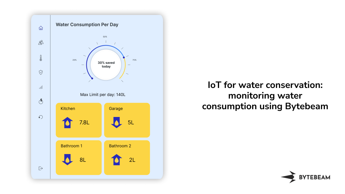
So to address this problem, I have created a solution to monitor water consumption using Bytebeam. This solution helps you monitor your water consumption and automate your water source with just one click of a button at any time from anywhere.
What to expect from this guide:
In this comprehensive blog post, we'll walk you through the step-by-step process of setting up this smart water meter solution using ESP32 and bytebeam. We will be demonstrating the following
- Setting up the Bytebeam cloud console: We will go through creating an account and setting up a new project on the Bytebeam cloud console.
- Setting Up ESP32: We will set up the water flow sensor. Integrate it with ESP32 to calculate water consumption values.
- Provisioning ESP32: We will provision ESP32 using provisioning JSON.
- Connecting an ESP32 to the Bytebeam platform: We will learn how to connect an ESP32 to the Bytebeam platform and how to send data from the device to the cloud.
- Creating a dashboard for data visualization: We will create a dashboard to monitor water consumption
Hardware and Software Specifications
Hardware Specification
Software Specification
Setting Up Bytebeam Cloud
If you are new to the Bytebeam IoT cloud platform. Go through the getting started with Bytebeam tutorial to deep dive into the concepts of Bytebeam. I hope you found the getting started guide useful and are aware of the concepts of Bytebeam Cloud.
- First, create a new device for that, Go to the Device Management panel and click on Create device
- As you hit submit in the prompt. A new JSON file will be downloaded which contains the authentication certificate, broker, device_id, and project ID. You need to save this file in the ESP file system. We will talk about this in a later section.

- The JSON will look like this.
{
 "project_id": "****",
 "broker": "******",
 "port": 8883,
 "device_id": "**",
 "authentication": {
      "ca_certificate":*"*********",
      "device_certificate": "**********",
      "device_private_key": "***********"
      }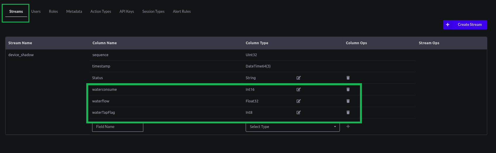
}- Next, We need to configure the stream according to our project in the Bytebeam cloud console. For that go to Settings -> Streams and add waterconsume, waterflow, and waterTapFlag in the column name with their respective data type.
Setting Up ESP32
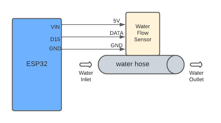
First, we need to integrate the water flow sensor with ESP32. The water flow sensor uses a Hall effect mechanism to calculate the flow rate. It contains a rotor, The speed of the rotor changes with the speed of the water flow. The hall-effect sensor senses it and outputs the corresponding pulse signal. I have already set it up with ESP32 and my setup looks like this.
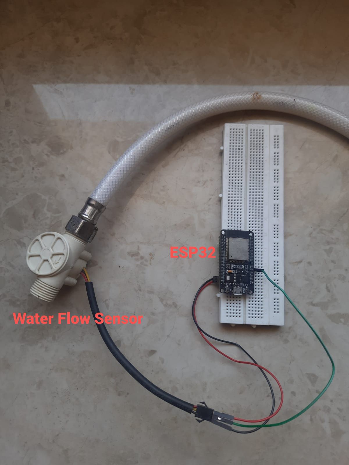
Hardware connection
First, get your Water Flow sensor. Connect the VCC and GND pins of the water flow sensor with the VIN and GND of ESP32. connect the data pin of the water flow sensor with GPIO 4 (It could be any, for the scope of this guide we have chosen this) of ESP32.
Firstly to get started with Bytebeam SDK for Arduino, you need to install the Bytebeam Arduino library. This can be downloaded from the Arduino library manager. To get more understanding of Bytebeam Arduino installation and provisioning of ESP32 go through our 3-part tutorial series:
Getting water consumption and flow rate values from ESP32
- Clone SmartWaterMeter repository from GitHub.
- Open the SmartWaterMeter project and upload it to ESP32
- Once the project has been flashed. Open the serial Monitor to debug the project.
Code Overview
- In src.ino. First, set up your water flow sensor pin. attach an interrupt to it to count the number of pulses
- 'flowPulse' represents the number of pulses counted during the time interval. This is determined by the interrupt that triggers every time the flow meter generates a pulse.
volatile int flowPulse = 0;
pinMode(FLOW_PIN, INPUT);
attachInterrupt(digitalPinToInterrupt(FLOW_PIN), pulseCounter, FALLING);- Now create a function for Interrupt Service routine
//ISR
void pulseCounter() {
  flowPulse++;
}- Next, Create a function to calculate the flow rate.
void calculateFlowRate(){
  //unsigned static long totalMilliLitres = 0;
  unsigned long currentMillis = millis();
  if (currentMillis - previousMillis > 1000) {
    detachInterrupt(digitalPinToInterrupt(FLOW_PIN));
    flowRate = ((1000.0 / (currentMillis - previousMillis)) * flowPulse) / 7.5; // Adjust the 7.5 accordingly based on your flow meter's specs
    RSTATE.flow = flowRate;
    previousMillis = currentMillis;
    flowPulse = 0;
    attachInterrupt(digitalPinToInterrupt(FLOW_PIN), pulseCounter, FALLING);

    if (flowRate >= 1.0 && flowRate <= 30.0) { // Check if flow rate is within the sensor's specified range
      unsigned int flowMilliLitres = (flowRate * 1000.0);
      Serial.printf("Water consumed(mL):%d\n", flowMilliLitres);
      RSTATE.consume = flowMilliLitres;
    }else{
      Serial.println("No flow rate");
      if(RSTATE.isWaterOn){
          RSTATE.isWaterOn = !RSTATE.isWaterOn;
      }
      RSTATE.consume = 0;
    }
}
}- In the above code, currentMillis - previousMillis calculates the time elapsed in milliseconds since the last flow rate calculation. It represents the time interval during which flow pulse pulses were counted.
flowRate = ((1000.0 / (currentMillis - previousMillis)) * flowPulse * 60) / 7.5;- flowRate = ((1000.0 / (currentMillis - previousMillis) computes the flow rate in pulses per second. By dividing 1000 by the elapsed time in milliseconds and multiplying it by 60, we get the flow rate in pulses per minute.
- 7.5 is a conversion factor that relates the number of pulses to millilitres of water. It's based on the specifications of your specific water flow meter. In our case, As per vendor documentation, 7.5 pulses represent 1 L of water. You may need to adjust this value based on your flow meter's documentation. If your flow meter's documentation states a different pulses-to-milliliters conversion factor, use that value instead.
flowMilliLitres = (flowRate * 1000.0);- flowRate * 1000 then converts the number of pulses per minute to millilitres of water per minute. This multiplication accounts for the conversion factor that relates pulses to millilitres. If you change the conversion factor, you should adjust this part of the code accordingly.
- Then publish the water consumption to Bytebeam.
bool publishToDeviceShadow()
{
  static int sequence = 0;
  const char *payload = "";
  String deviceShadowStr = "";
  StaticJsonDocument<1024> doc;

  char deviceShadowStream[] = "device_shadow";

  sequence++;
  unsigned long long milliseconds = getEpochTime();

  JsonArray deviceShadowJsonArray = doc.to<JsonArray>();
  JsonObject deviceShadowJsonObj_1 = deviceShadowJsonArray.createNestedObject();
  DEBUG_PRINTLN(milliseconds);

  deviceShadowJsonObj_1["timestamp"] = milliseconds;
  deviceShadowJsonObj_1["sequence"] = sequence;
  if (!RSTATE.isWaterOn)
  {
    deviceShadowJsonObj_1["Status"] = "water tap On";
  }
  else
  {
    deviceShadowJsonObj_1["Status"] = "water tap off";
  }
  deviceShadowJsonObj_1["waterflow"] = RSTATE.flow;
  deviceShadowJsonObj_1["waterconsume"] = RSTATE.consume;
  deviceShadowJsonObj_1["watertapflag"] = RSTATE.isWaterOn;

  serializeJson(deviceShadowJsonArray, deviceShadowStr);
  payload = deviceShadowStr.c_str();
  Serial.printf("publishing %s to %s\n", payload, deviceShadowStream);
  return Bytebeam.publishToStream(deviceShadowStream, payload);
}
Visualizing water consumption data on Bytebeam Cloud
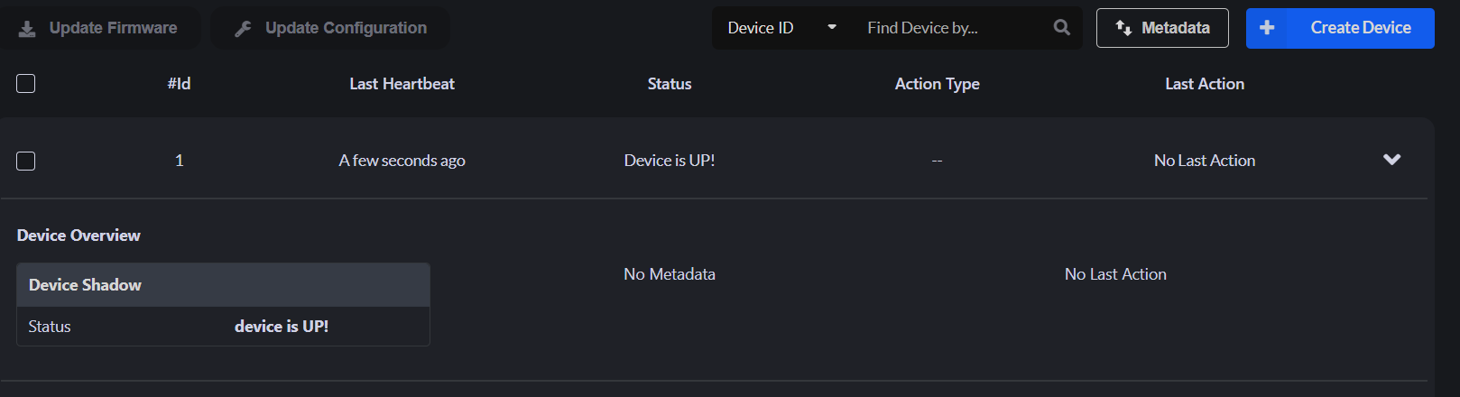
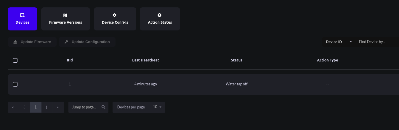
- After the Successful connection of ESP32 with Bytebeam Cloud. We can see the recent device shadow and heartbeat on the cloud console.
- Now let’s create a dashboard to visualize our data. Follow the Data Visualization Getting Started guide to create Dashboards and visualizations of your choice.
- Now to monitor water consumption, Let's create visualization panels. First, create a line chart to monitor the flow rate (mL/per second).
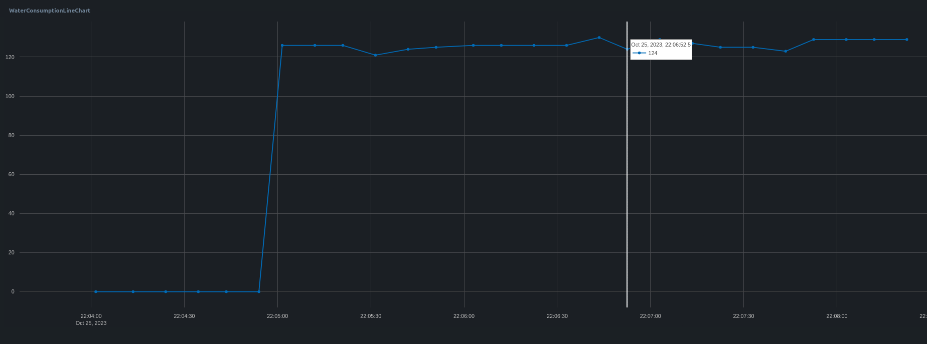
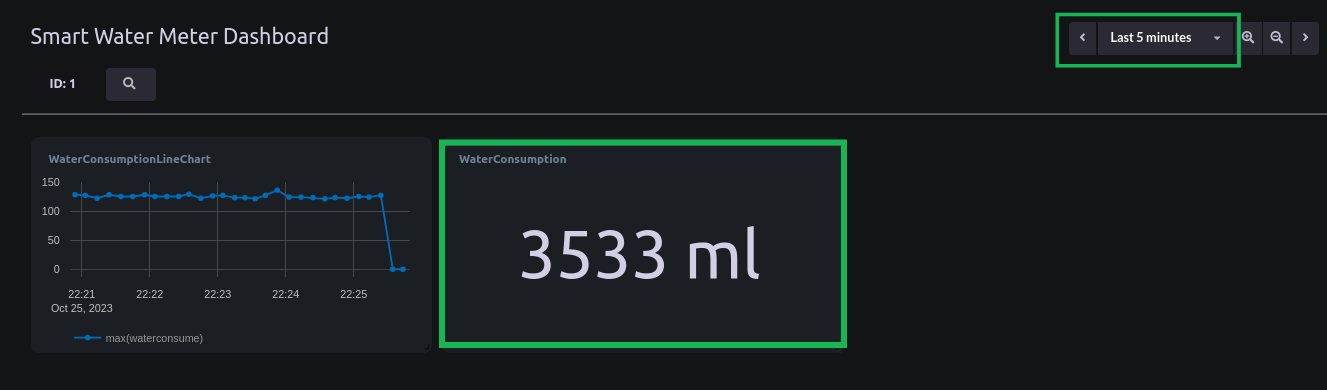
- The above graph shows only the water consumed per second. To calculate the total water consumed during a certain duration, Let's create an Aggregate Value visualization panel. Using sum as an aggregator we can calculate the total water consumption
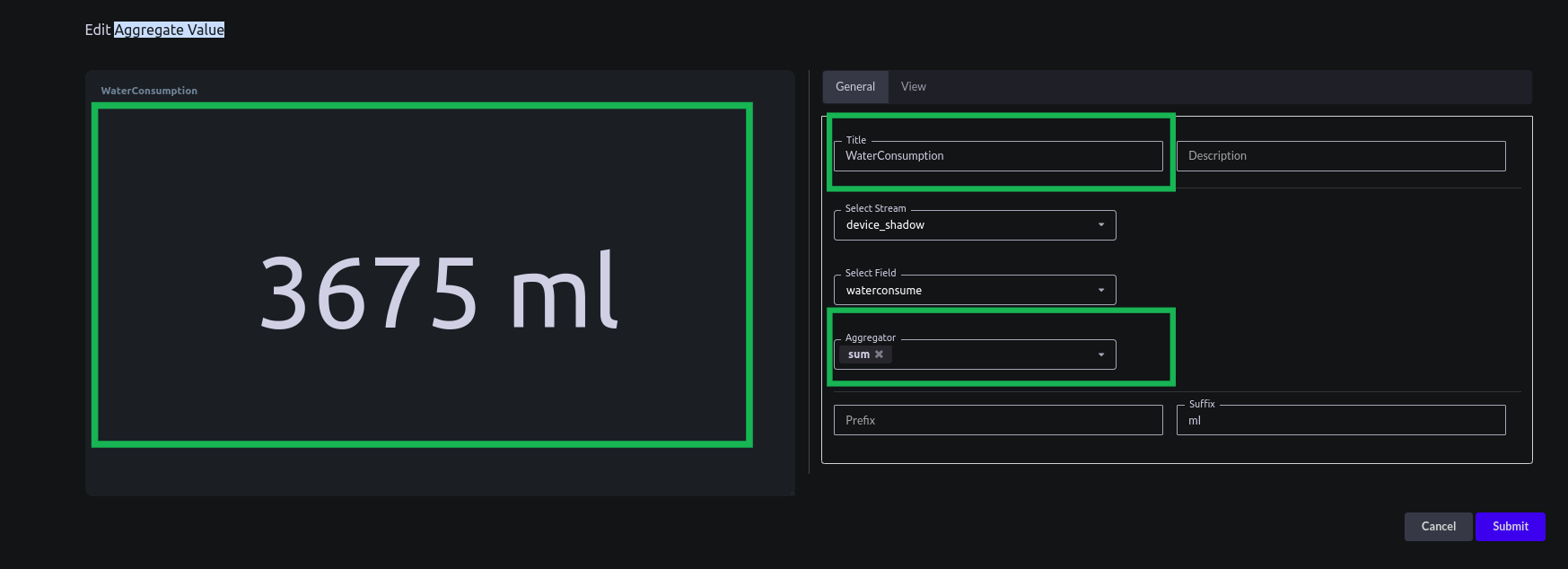
- Here is the consumption of water in 5 mins
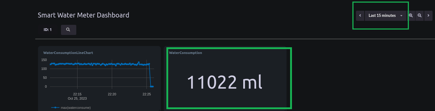
- Here is the consumption of water in 15 mins
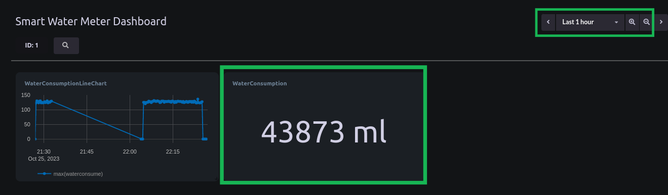
- Here is the consumption of water in 1 hour

Conclusion
I hope you find this tutorial useful. We will come up with other interesting use cases using ByteBeam.
Explore other exciting features of the Bytebeam Arduino SDK! Check out our OTA guide for remote updates and the Handling Action Guide for remote operations.
As we continue to come up with more interesting tutorials and maker content, we invite you to explore Bytebeam further and see how our platform can empower your projects.
Stay tuned!


.png)
